|
|
![]()
Topological relations
Topology deals with spatial and structural properties of geometric objects, independent of their extension, type, or geometric form. Among the types of topological properties of objects there are: the number of dimensions an object has or the relationships that exist between objects. All topological properties are invariant to any continuous deformation of space (Saaty 1980). The topology simplifies analysis functions, as the following examples show: joining adjacent areas with similar properties. It is important to distinguish between vector data formats and raster data formats. For example, imagine an area represented by a vector data model: it is composed of a border, which separates the interior from the exterior of the surface. The same area represented by a raster data model consists of several grid cells. There is no border existing as a separating line. Thus, the algorithms implemented for vector data models are not valid for raster data models. In the following example, we only show topological operations in vector data models.
VECTOR An interesting method for the classification of topological relations was proposed by Egenhofer (1993) (Worboys et al. 2004). It is called the 9‐intersection schema. This intersection scheme is an elegant approach for the classification of topological configurations. The basic idea is based on the concept that each element is composed of a boundary (b), an interior (i), and an exterior (e). The concept of interior, boundary and complement (exterior) are defined in the general topology.
Boundary
The boundary consists of points or lines that separate the interior from the exterior. The edge of a line consists of the endpoints. The boundary of a polygon is the line that defines the perimeter.
Interior
The interior of an object consists of points, lines or areas that are in the object but do not belong boundary.
Complement
The complement, also called exterior, consists of the points, lines and areas which are not in the object.
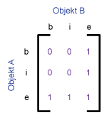
The basic method used to compare two geometrical objects is to analyze the intersections between all the possible pairs that can be built with the interior, exterior and boundary of these two objects. Based on the resulting "intersection" matrix, the relationships between the two geometrical objects can be classified.
Two objects, A and B, are given. Both of them are represented by their interior (i), boundary (b) and
exterior (e). There are nine possible relations of these two geometrical objects. They are shown in the
following table.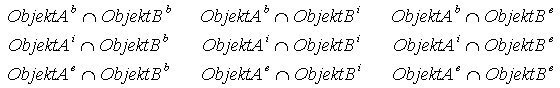
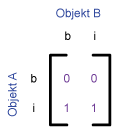
The 4‐intersection‐matrix is sometimes used as basis for the analysis of topological relations. It is
generated by omitting the components of the exterior. It is less powerful than the 9‐intersectionmatrix. 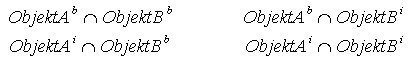
The most important topological relations between objects that are used in GIS applications are listed in the following sequence. Note that there are three different geometries (point, line, polygon) on which the topological relations are applied.
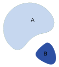
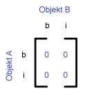
Disjoint
There is no intersection area between object A and object B. Test for disjoint.
Meet
Object A and object B meet at the boundary. The boundaries meet, but not the interior. Two geometry objects meet if the boundaries touch. Test for touch.
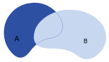
Overlap
Object A and object B overlap.
Test for intersect (inversion of disjoint).
Overlap with disjoint: The interior of an object
intersects the boundary and the interior of the other
object, but the boundaries do not intersect. That is the case if a line starts outside a polygon (area)
and ends in the interior of the polygon.
Overlap with Intersect: The boundaries and the
interior of both objects intersect. If a geometry
object has to intersect another geometry object the geometry needs to be part of the dimension of
the bigger object. That means:
- Points
- Cannot intersect with points, lines or areas. - Lines
- Cannot intersect with points.
- Can intersect with other lines » intersection = point.
- Can intersect with polygons » intersection = lines (or points).
Contains
Object A contains object B. Test whether the initial geometry object encloses a different geometry object. The interior and the boundary of an object are completely inside of the other object. A geometry object cannot contain a geometry object of higher order. E.g.:
- Points can not contain lines or polygons.
- Lines can not contain polygons.
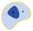
Inside
Object B lies inside object A. It is the opposite of "contain". If A is inside B, then B contains A.
Covers
Object A covers object B. The interior of an object is completely inside the other object and the boundaries intersect. A geometry object can’t include a geometry object of higher dimension. That means:
- Points can not contain lines or polygons.
- Lines can not contain polygons.
Covered by
Object B is covered by object A. It is the opposite of "covers". If A is covered by B, then B covers A.
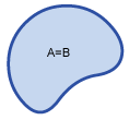
Equal
Object B and object A match. Test for equality of the initial geometry object and a different geometry object. The interior and the boundary of an object are lying on the boundary of the other object and vice versa. This happens when a line falls exactly on the boundary of a polygon. The coordinates of all components have to be equal. The compared geometry objects must be equal. That means:
- Point = point
- Line = line
- Polygon = polygon
The following table shows the most common topological relations:
| poly-poly | line-line | point-point | poly-line | poly-point | line-point | |
|---|---|---|---|---|---|---|
| Disjoint |
 |
 |
|
 |
 |
 |
| Meet |
 |
 |
|
|
 |
 |
| Overlap |
 |
 |
|
 |
|
|
| Contains |
 |
|
|
 |
 |
|
| Inside |
 |
|
|
 |
 |
|
| Covers |
 |
|
|
 |
|
|
| Covered by |
 |
|
|
 |
|
|
| Equal |
 |
 |
|
|
|
|
The following table shows the 9‐intersetion‐schema and the 4‐intersection‐schema for some typical
topological relations between two polygons, proposed by Egenhofer et al.
(1993). The relations are
given by the values 0 and 1. Every pair has an empty (0) or an occupied (1) intersection.
| Topological relation | Graphical description | 4-intersection-matrix | 9-intersection-matrix |
|---|---|---|---|
| Disjoint |
 |
 |
 |
| Meet |
 |
 |
 |
| Overlap |
 |
 |
 |
| Contains |
 |
 |
 |
| Inside |
 |
 |
 |
| Covers |
 |
 |
 |
| Covered by |
 |
 |
 |
| Equal |
 |
 |
 |
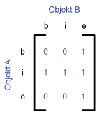
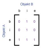
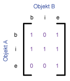
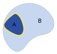
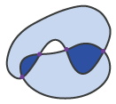
There is at least one disadvantage in this model: there is no possibility to conceptually separate
different situations.
 |
 |
 |
These three situations presented correspond to the following matrix:
|
|
|
|